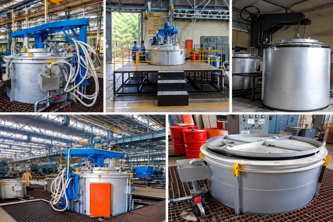
When you look at a Pit Furnace Diagram, the first thing that stands out is the vertical arrangement of the furnace. Unlike a conventional horizontal furnace, a pit furnace has a deep heating chamber and is generally loaded from the top. This arrangement makes the furnace particularly useful for long, heavy or vertically positioned components that can be difficult to process in a conventional chamber.
A diagram also makes it easier to understand what happens inside the furnace. The heating chamber, insulation, heating elements or burners, circulation system, temperature sensors, lid and loading arrangement all have a specific function. When these components work together correctly, the furnace can provide controlled heating for demanding industrial heat treatment applications.
For engineers, maintenance teams and students, understanding a Pit Furnace Diagram is therefore more useful than simply knowing the definition of a pit furnace.
What Is a Pit Furnace?
A pit furnace is a vertical industrial furnace in which the heating chamber extends below the normal floor level or is constructed as a deep vertical chamber. Components are generally loaded from the top and positioned inside the chamber before the furnace is closed.
The vertical configuration is especially practical when the job involves long shafts, rolls, rods, gears, forgings or other components that benefit from vertical positioning.
In real production, component handling can be just as important as temperature control. A long component that is difficult to support horizontally can often be positioned more conveniently inside a vertical pit furnace.
JR Furnace manufactures pit furnace systems for industrial heat treatment applications, including designs with electric or fuel-fired heating, controlled atmospheres and circulation systems.
Pit Furnace Diagram and Its Main Components
A typical Pit Furnace Diagram shows the major components arranged around the vertical heating chamber. Although the exact construction changes according to capacity, temperature, atmosphere and application, the basic arrangement remains similar.
1. Furnace Shell
The outer shell provides the structural body of the furnace. It supports the refractory lining, insulation, heating system and other mechanical components.
The shell must be strong enough to withstand the operating conditions of the furnace while also providing a stable structure for the lid and loading arrangement.
2. Insulation and Refractory Lining
The inner walls of a pit furnace are protected by refractory and insulating materials. Their purpose is to retain heat inside the chamber and reduce heat transfer to the external structure.
The choice of lining depends on operating temperature, furnace construction and the type of material being processed.
A properly designed lining also helps maintain temperature stability throughout the heating cycle.
3. Heating Chamber
The heating chamber is the working area shown in the central portion of a Pit Furnace Diagram.
This is where the components are placed during heat treatment. Its dimensions are selected according to the required load size, component geometry and production requirements.
For vertical processing, the chamber depth becomes particularly important because the workpiece must fit safely within the available heating zone.
4. Heating Elements or Burners
The heating system depends on the furnace design.
In an electrically heated pit furnace, resistance heating elements are normally positioned around the furnace chamber. In a fuel-fired design, burners provide the required heat through a controlled combustion system.
JR Furnace’s pit furnace designs can use electric, gas-fired or oil-fired heating depending on the application.
The heating arrangement is important because the objective is not simply to reach a high temperature. The furnace must also maintain the required temperature throughout the working zone.
5. Temperature Sensors
Temperature sensors monitor the temperature inside the furnace.
The measured temperature is transmitted to the control system, which regulates the heating output according to the programmed cycle.
For industrial heat treatment, accurate temperature measurement is essential because the final properties of a component can depend on the heating rate, soaking temperature and holding time.
6. Recirculation Fan
Some pit furnaces use a circulation fan to move heated air or atmosphere around the load.
This is particularly important in convection-based designs because stagnant air can produce temperature differences between different areas of the chamber.
A properly designed circulation system helps improve heat transfer and temperature uniformity. JR Furnace specifies axial or centrifugal recirculation arrangements for its pit furnace designs depending on the application.
7. Furnace Lid
The lid closes the top of the furnace after the components have been loaded.
Depending on the furnace design, the lid may be manually operated or hydraulically lifted and moved away from the furnace opening to allow loading and unloading.
For atmosphere-controlled applications, the lid and sealing arrangement become especially important because unwanted air entering the chamber can affect the heat treatment process.
8. Loading Arrangement
Because the furnace is vertical, loading is normally performed from the top.
An EOT crane or suitable loading equipment can be used to lower the components into the chamber.
This arrangement is one of the main reasons pit furnaces are suitable for heavy and elongated components.
9. Atmosphere Control System
Some heat treatment processes require more than temperature control.
When oxidation, decarburization or surface reactions need to be controlled, a sealed retort or controlled atmosphere system can be incorporated into the furnace.
Depending on the process, gases such as nitrogen, ammonia or hydrocarbon-rich gases may be introduced into the controlled chamber.
The exact atmosphere depends on the metallurgical process and material being treated.
How Does a Pit Furnace Work?
Understanding the Pit Furnace Diagram becomes easier when the operation is considered step by step.
First, the furnace is prepared according to the required heat treatment cycle. The components are then loaded vertically into the chamber using suitable handling equipment.
Once the load is positioned correctly, the lid is closed. The heating system begins raising the temperature according to the programmed cycle.
As the temperature increases, sensors continuously monitor the furnace conditions. The control system adjusts the heating output to maintain the required temperature.
If the furnace uses forced circulation, the fan moves heated air around the components to improve temperature distribution.
Once the required temperature is reached, the load is held at that temperature for the specified soaking period. This allows the component to reach a more uniform temperature throughout its section.
After soaking, the furnace follows the required cooling or quenching procedure. The cooling method depends on the particular heat treatment process.
The complete cycle can therefore be understood as loading, heating, soaking and controlled cooling.
Why Is the Vertical Design Important?
The vertical arrangement is not simply a different way of building a furnace.
For long components, horizontal loading can introduce practical problems related to support, handling and deformation. A vertical arrangement can provide a more suitable method of positioning such components.
This is particularly relevant for shafts, rolls, rods and other elongated components.
The design also makes top loading possible, which can simplify handling when an overhead crane is already available in the production area.
However, the correct furnace should always be selected according to the component dimensions, weight, heat treatment process, production volume and required atmosphere.
What Materials and Components Can Be Heat Treated?
Pit furnaces are used across several industrial applications.
Typical components may include gears, shafts, rolls, forgings, fasteners, bearings and other steel components. Depending on the furnace design, they can also support applications involving aluminium components and other materials.
The process performed inside the furnace depends on the material and required metallurgical result.
Common processes include annealing, normalizing, hardening, tempering, carburizing, carbonitriding, nitriding and stress relieving. JR Furnace lists these processes among the applications of its pit furnace systems.
Electric vs Fuel-Fired Pit Furnace
A Pit Furnace Diagram may look similar from the outside even when the heating systems are completely different.
An electric pit furnace uses resistance heating elements to generate heat. These elements can be arranged in multiple zones so that temperature control can be adjusted across the furnace chamber.
A fuel-fired pit furnace uses burners and a combustion control system to generate heat.
The choice between electric and fuel-fired heating depends on factors such as available energy source, operating temperature, production requirements, atmosphere requirements and operating economics.
There is no single heating arrangement that is suitable for every industrial application.
Where Are Pit Furnaces Used?
Pit furnaces are commonly considered when the workpiece is large, heavy, long or better suited to vertical loading.
They can be used in industries associated with steel components, automotive parts, forgings, gears, bearings, fasteners and other engineered products.
The furnace can also be configured for different heat treatment requirements. For example, a basic furnace may be designed for heating and soaking, while a more advanced system can incorporate controlled atmosphere, recirculation, automated temperature control and quenching facilities.
This flexibility is one reason pit furnaces remain relevant in industrial heat treatment.
What Should You Check Before Selecting a Pit Furnace?
Pit Furnace Diagram shows the basic furnace construction, but selecting an industrial furnace requires more information.
The first consideration is the component itself. Its length, diameter, weight, material and loading method determine the required chamber dimensions and capacity.
The next consideration is the process. Annealing, hardening, tempering, carburizing and nitriding do not necessarily require the same furnace configuration.
Temperature range is another important factor. The heating elements, refractory system, insulation and instrumentation must all be appropriate for the required operating temperature.
Atmosphere requirements should also be considered when surface protection or controlled chemical reactions are part of the process.
Finally, the control system, safety arrangements, loading equipment, energy source and production cycle should be evaluated together rather than separately.
Pit Furnace Diagram: Understanding the Complete System
A Pit Furnace Diagram is more than a simple drawing of a furnace chamber. It represents how several systems work together to achieve controlled industrial heating.
The furnace shell provides structural support. The refractory and insulation retain heat. Heating elements or burners generate the required temperature. Sensors measure operating conditions, while the control system regulates the heating cycle. Circulation equipment helps distribute heat, and the lid and atmosphere system provide the necessary enclosure.
When these components are correctly matched to the application, a pit furnace can provide repeatable heat treatment for heavy and elongated industrial components.
For manufacturers, the most important point is that furnace design should begin with the actual production requirement rather than choosing equipment based only on furnace size or maximum temperature.
Pit Furnace vs Other Industrial Furnaces
Different furnace designs are intended for different loading and production requirements.
| Furnace Type | Loading Arrangement | Typical Use |
|---|---|---|
| Pit Furnace Diagram | Vertical | Long, heavy and vertically loaded components |
| Bogie Hearth Furnace | Horizontal | Large and heavy components |
| Chamber Furnace | Horizontal | Batch heat treatment |
| Pusher Furnace | Continuous | Higher-volume production |
| Mesh Belt Furnace | Continuous | Smaller components and continuous processing |
Frequently Asked Questions About Pit Furnace Diagram
What does a pit furnace diagram show?
A Pit Furnace Diagram generally shows the furnace shell, refractory lining, heating chamber, heating elements or burners, temperature sensors, circulation system, lid and loading arrangement. More advanced diagrams may also show atmosphere control, retorts, quenching systems and exhaust arrangements.
How is a pit furnace loaded?
Pit furnaces are normally loaded from the top. Heavy components can be lowered into the chamber using an EOT crane or suitable loading equipment.
What is the main advantage of a vertical pit furnace?
The vertical arrangement is particularly useful for long or heavy components that may be difficult to support or position horizontally.
What is a pit furnace diagram?
A pit furnace diagram is a visual representation of a vertical furnace showing components such as the furnace chamber, heating system, insulation, lid, workpiece, thermocouples, and control arrangement.
Final Thoughts
Looking at a Pit Furnace Diagram gives you a clear picture of how the major furnace components fit together, but the real engineering decisions happen around the application.
The required temperature, load weight, component dimensions, heating method, atmosphere, circulation, control system and cooling method all influence the final furnace design.
For industrial heat treatment, a pit furnace is therefore not simply a deep chamber with a heater. It is a complete thermal processing system designed around the material, component geometry and required heat treatment cycle.
JR Furnace & Ovens manufactures industrial furnace systems for heat treatment applications and offers pit furnace configurations for different industrial requirements